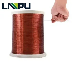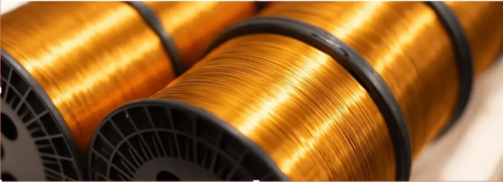
Bunched Solderable Polyurethane Enamelled Round Copper Wire Class 130
- General notes on methods of test
- Dimensions
- Electrical resistance
- Flexibility and adherence
- Solderability
- Packaging
The type of packaging can affect certain properties of the wire, such as flexibility and adherence. Therefore, the type of packaging, including the type of spool, must be mutually agreed upon by the purchaser and supplier. The wire should be wound evenly and compactly on spools or placed in containers. No spool or container should contain more than one length of wire unless otherwise agreed upon by the purchaser and supplier. The labeling of the package, when it contains more than one length, and the identification of separate lengths within the package should also be mutually agreed upon by the purchaser and supplier.

IEC 60317-0-11 standard provides comprehensive technical requirements for class 130 bunched solderable polyurethane enameled round copper wire. These requirements cover the thermal, electrical and mechanical properties of the wire, ensuring excellent performance under a variety of usage conditions.

All testing methods referred to in this standard are outlined in IEC 60851. The clause numbers in this standard correspond to the respective test numbers in IEC 60851. In case of any discrepancies between the testing methods publication and this standard, IEC 60317-11 shall take precedence. If no specific range of nominal conductor diameters is indicated for a test, the test is applicable to all nominal conductor diameters covered by the specification sheet.
Unless otherwise specified, all tests should be conducted at temperatures between 15°C and 35°C and relative humidity between 45% and 75%. Prior to taking measurements, specimens must be conditioned in these atmospheric conditions for a sufficient period to achieve stability.
The bunched wire to be tested should be carefully removed from its packaging to avoid tension or unnecessary bends. Before conducting each test, enough wire should be discarded to ensure that any damaged bunched wire is excluded from the test specimens.
2.1 Maximum overall diameter of the single wire
The maximum overall diameter of the single wire shall be in accordance with the appropriate value given in table 1.
Table 1- Maximum overall diameter of the single wire
| Nominal conductor
diameter mm |
Maximum overall
diameter ww |
| 0,025
0,032 0,040 0,050 0,063 0,071 0,100 0,125 0,200 0,315 0,400 |
0,031
0,039 0,049 0,060 0,076 0,084 0,117 0,144 0,226 0,349 0,439 |
| NOTE The conductor diameters and maximum overalldiameters are in accordance with IEC 60317-0-1 forgrade 1. | |
2.2 Overall diameter of the bunched wire
The number of wires and the nominal overall diameter shall be in accordance with those given in table 2.
The figures given in table 2 are related to the measurement on a mandrel. The real figures, measured with a microscope, are approximately 8 % lower.
The maximum figures, when tested on the mandrel, shall not be more than 10 % higher than the figures given in table 2.
Table 2 – Nominal overall diameters
| Number of wires | Nominal conductor diameter of the single wire | ||||||||||
| 0,025 | 0,032 | 0,040 | 0,050 | 0,063 | 0,071 | 0,100 | 0,125 | 0,200 | 0,315 | 0,400 | |
| Nominal overall diameter(mm) | |||||||||||
| 3
4 5 6 8 10 12 16 20 25 32 40 60 100 160 250 |
0,095
0,105 0,115 0,120 0,135 0,145 0,160 0,180 0,195 0,220 0,240 0,265 0,320 0,405 0,505 0,625 |
0,115
0,125 0,135 0,145 0,165 0,180 0,195 0,220 0,245 0,270 0,300 0,330 0,400 0,510 0,635 0,815 |
0,130
0,150 0,160 0,175 0,195 0,215 0,230 0,265 0,295 0,325 0,365 0,405 0,495 0,625 0,810 0,995 |
0,155
0,175 0,190 0,205 0,235 0,260 0,280 0,320 0,355 0,395 0,445 0,500 0,605 0,795 0,990 1.230 |
0,190
0,215 0,235 0,255 0,285 0,315 0,345 0,395 0,440 0,500 0,560 0,620 0,780 0,985 1.240 1.530 |
0,205
0,235 0,255 0,275 0,315 0,350 0,380 0,435 0,490 0,550 0,615 0,715 0,860 1,100 1,370 1,695 |
0,250
0,285 0,315 0,340 0,385 0,430 0,465 0,540 0,605 0,705 0,790 0,875 1,055 1,355 1,695 2,100 |
0,305
0,345 0,380 0,415 0,475 0,530 0,580 0,695 0,775 0,865 0,970 1,085 1,315 1,675 2,100 2,605 |
0,465
0,540 0,595 0,675 0,770 0,855 0,930 1,085 1,210 1,355 1,525 1,695 2,060 2,635 3,315 4,125 |
0,745
0,855 0,945 1,030 1,190 1,320 1,440 1,665 1,865 2,090 2,355 2,625 3,200 4,105 5,175 6,450 |
0,930
1,065 1,195 1,300 1,490 1,655 1,805 2,090 2,345 2,635 2,970 3,315 4,040 5,195 6,550 8,170 |
| NOTE 1 The number of wires is taken from the R series of numbers, rounded for technical reasons.
NOTE 2 Above the line, normally one silk layer is applied and below the line, a double silk layer is applied. NOTE 3 The overall diameters are calculated according to the method given in annex A and measured according to IEC 60851. NOTE 4 Where, for technical reasons, the combinations of wires given in table 2 are not sufficient, other combinations can be agreed between purchaser and supplier. The single wire shall then be taken from IEC 60317-0-1. |
|||||||||||
2.3 Length of lay
The length of lay shall not exceed 60 mm and shall have an “S” twist (counter-clockwise).
The resistance at 20 ℃ shall be within the limits given in table 3.
Table 3-Electrical resistances
| Number of wires | Nominal conductor diameter of the single wire (mm) | |||||||||||||||||||||
| 0,025 | 0,032 | 0,040 | 0,050 | 0,063 | 0,071 | 0,100 | 0,125 | 0,200 | 0,315 | 0,400 | ||||||||||||
| Resistance (Ω/m) | ||||||||||||||||||||||
| Min. | Max. | Min. | Max. | Min. | Max. | Min. | Max. | Min. | Max. | Min. | Max. | Min. | Max. | Min. | Max. | Min. | Max. | Min. | Max. | Min. | Max. | |
| 3
4 5 6 8 10 12 16 20 25 32 40 60 100 160 250 |
10.45
7,835 6,268 5,223 3,918 3,134 2,612 1,959 1,567 1,254 0,979 0,784 0,522 0,313 0,196 0,125 |
13.03
9,769 7,815 6,513 4,885 3,908 3,256 2,442 1,954 1,563 1,258 1,006 0.684 0.410 0.261 0,167 |
6,377
4,783 3,826 3,188 2,391 1,913 1,594 1,196 0.957 0.765 0.598 0,478 0,319 0,191 0,120 0,0765 |
7,949
5,962 4,770 3,975 2,981 2,385 1,987 1,490 1,192 0,954 0,768 0,614 0,417 0,250 0,160 0,102 |
4,093
3,070 2,456 2,047 1,535 1,228 1,023 0,768 0,614 0.491 0,384 0,307 0.205 0,123 0.0768 0,0491 |
5,073
3,805 3,044 2,536 1,902 1,522 1,268 0,951 0,761 0.690 0.490 0,392 0.266 0,160 0.102 0.0652 |
2,641
1,981 1,584 1,320 0,990 0,792 0,660 0,495 0,396 0,317 0,248 0,198 0.132 0.0792 0.0495 0,0317 |
3,226
2,420 1,936 1,613 1,210 0,968 0,807 0,605 0,484 0,387 0,312 0,249 0.169 0,102 0.0648 0.0414 |
1,682
1,261 1,009 0,841 0.631 0,505 0,420 0,315 0,252 0.202 0.158 0,126 0.0841 0.0505 0,0315 0.0202 |
2,013
1,510 1,208 1,007 0.755 0,604 0,503 0,378 0,302 0,242 0,194 0,156 0,106 0.0634 0.0404 0.0259 |
1,314
0,985 0,788 0,657 0,493 0,394 0,328 0,246 0.197 0,158 0,123 0,0985 0.0657 0.0394 0.0246 0,0158 |
1,614
1,210 0,968 0,807 0,605 0,484 0,403 0,303 0,242 0.194 0.156 0,125 0.0847 0.0508 0.0324 0.00207 |
0,678
0,509 0,407 0,339 0,254 0,203 0,170 0,127 0.102 0.0814 0.0636 0,0509 0,0339 0.0203 0,0127 0,00814 |
0,793
0,595 0,476 0,397 0,297 0,238 0,198 0,149 0,119 0.0952 0.0766 0.0613 0,0417 0.0250 0,0159 0.0102 |
0,439
0,329 0.263 0,220 0.165 0,132 0,110 0.0832 0.0659 0.0527 0.0412 0.0329 0.0220 0.0132 0.00823 0.00527 |
0,502
0,376 0,301 0,251 0,188 0.150 0,125 0,0940 0.0752 0.0602 0.0484 0,0387 0,0263 0.0158 0,0101 0.00644 |
0,175
0,131 0,105 0.0873 0.0655 0.0524 0.0436 0,0327 0.0262 0.0209 0.0164 0.0131 0.00873 0.00524 0.00327 0.00209 |
0,192
0,144 0,115 0.0962 0.0721 0.0577 0,0481 0.0361 0.0289 0.0231 0.0186 0.0149 0.0101 0.00606 0.00386 0.00247 |
0,0707
0.0530 0.0424 0.0354 0.0265 0.0212 0.0177 0.0133 0.0106 0.00848 0.00663 0.00530 0.00354 0.00212 0.00133 0.000848 |
0.0772
0,0579 0,0463 0,0386 0,0289 0.0232 0.0193 0,0145 0.0116 0.00926 0.00745 0.00596 0.00405 0.00243 0.00155 0.00166 |
0.0439
0,0329 0.0263 0.0219 0.0165 0.0132 0.0110 0.00823 0.00658 0.00526 0.00411 0.00329 0.00219 0.00132 0.000823 0.000526 |
00000
0,0375 0,0300 0.0250 0.0187 0.0150 0,0125 0.00937 0.00750 0.00600 0.00483 0.00386 0.00262 0.00157 0.00100 0.000642 |
| Above the line- the maximum resistance has been calculated for 1x bunched,between the lines and for 2x bunched,and below the line-for 3x bunched. | ||||||||||||||||||||||
Mandrel Test
The bunched enamelled copper wires must be covered with one or two layers of silk. The first layer should be applied in the opposite direction to the twist of the bunched wires. If a second layer is used, it should be wound in the opposite direction to the first layer.
The covering should be consistent in quality, with each layer being even and uniform. When tested according to the method described in IEC 60851, the silk covering must not open sufficiently to clearly expose the enamelled wire.
The mandrel diameter used in the test should be approximately 10 times the overall diameter as specified in Table 2.
The silk covering shall be removed. Temperature of the solder bath shall be 375 ℃ ±5 °℃. The immersion time shall be as specified in table 4.
Table 4 – Immersion time
| Nominal cross-sectional area
of the bunched wires ww |
Immersion
time S |
|
| Over | Up to and
including |
|
| –
0,080 0,125 0,200 0,300 0,500 0,800 |
0,080
0,125 0,200 0,300 0,500 0,800 – |
3
4 5 6 8 10 As agreed |
The solder shall penetrate the whole of the bunch and the outside shall be a smooth coating with evidence of effective tinning.
For wires delivered in coils, the dimensions and maximum weights of the coils should be agreed upon by the purchaser and supplier. Any additional protective measures for the coils should also be determined by mutual agreement between the purchaser and supplier.
