Continuously Transposed Conductor CTC
Continuously transposed conductor CTC also called Transposed transmission line or transposed conductor is used in medium and ultra-high power transformers in electrical equipment, Transmission and distribution centers, Military and defense etc.
What is Continuously Transposed Conductor?
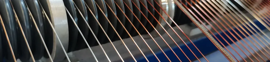
Transposition conductor is made of a certain number of enameled flat wires arranged in two columns in sequence by special technology, and made of special insulating materials. It consists of a group of enameled rectangular wires, usually with PVF (polyvinylformal) enamel, which are transposed to create a kind of rectangular strand.
In the CTC, each elementary conductor consecutively and repeatedly assumes every possible position inside the cable. The bundle of strips can be wrapped and insulated with tapes, generally in pure cellulose paper. CTC configurations come in different lengths to best suit the diameter of transformer windings for different applications and they may also contain between five and 73 wire strands. The finished product is used in power transformers as winding wires.
Continuously Transposed Cable CTC – Advanatges
1. Cost-effectiveness. CTCs can be used with small, less-expensive transformers to reduce the overall cost of the system. The thin insulation helps reduce the space demand for the windings.
2. Ease of use. CTCs have improved winding capabilities. They are also simple for operators and machinery to handle.
3. Reduce electrical loss. CTCs reduce the electrical losses that transformers suffer. They offer faster winding for shortened winding times. CTC windings also help reduce eddy current losses at the end of the winding.
4. Even distribution of heat. Electrical equipment often generates high levels of heat that may damage surrounding components or diminish overall performance. The insulation and spacing improvements that CTCs offer ensures that this heat is evenly distributed across the winding.
5. Improved mechanical strength. CTCs—especially self-bonding CTC types—offer better mechanical strength than alternative materials.
CTC wire Specifications
| Transposition number | 5 – 80 (odd or even optional) |
| Maximum dimension | height 120 mm, width 26 mm (tolerance ± 0.05 mm) |
| Single conductor size | thickness a: 0.90 – 3.15 mm, width B: 2.50 – 13.00 mm (tolerance ± 0.01 mm) |
| The recommended width thickness ratio of a single conductor | 2.0 < B / a < 9.0 |
| The recommended coating thickness of enameled wire | 0.08-0.12mm |
| The thickness of adhesive layer | 0.03-0.05mm |
Structure and Design
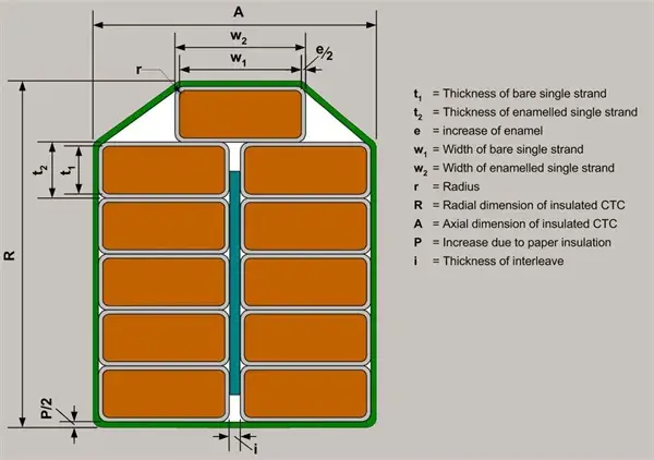
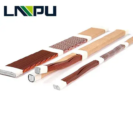
1. Composition:
CTC consists of multiple (typically 5 to 80) individually insulated rectangular or trapezoidal wire strands.
These strands are bundled together and transposed, meaning their positions are periodically swapped along the length of the conductor.
2.Transposition:
The transposition process involves rotating the positions of the strands within the bundle. This helps in averaging out the magnetic fields experienced by each strand, reducing localized hot spots and minimizing losses.
3. Insulation:
Each strand is coated with an enamel insulation. The entire bundle may also be wrapped in additional insulation for protection and structural integrity.
Applications
Power Transformers: Widely used in the windings of high-voltage and high-power transformers due to the efficiency and thermal management benefits.
Large Inductors and Reactors: Employed in the construction of large inductors and reactors where managing eddy current losses and heat dissipation is crucial.
Motors and Generators: Used in high-power motors and generators to improve performance and efficiency.