My Hard-Won Secrets to Mastering 35 Gauge Magnet Wire
- Incredible Winding Density: Its fine diameter allows you to pack an astonishing number of turns into a very small bobbin. This is the key to achieving high inductance in a compact footprint, essential for miniature solenoids, relays, and certain audio pickups.
- Excellent High-Frequency Performance: Due to its small cross-sectional area, 35 AWG wire is less susceptible to “skin effect” at higher frequencies compared to thicker wires. This makes it a prime candidate for RF chokes and impedance-matching transformers.
- Extreme Fragility: The tensile strength is minuscule. A sudden jerk, a slight snag on the spool, or inconsistent tension from your winding machine will break it instantly.
- Delicate Insulation: The enamel coating (often polyurethane for solderability or polyester-imide for durability) is microns thin. The slightest burr on a bobbin flange or a rough guide wheel can scrape it, creating an invisible short circuit that will haunt you during final testing.
- Soldering Finesse Required: It demands a surgeon’s touch. Too little heat and you get a cold joint; too much, and the wire vanishes or the insulation chars, preventing a good connection.
- Bobbin Preparation: I was using a standard nylon bobbin. I hadn’t inspected it under magnification. It had a tiny piece of flashing—a minuscule ridge of plastic left over from the molding process—on the inside edge of the flange. During winding, this “dull knife” was intermittently scraping the insulation on every single layer.
- “Static Cling” Contamination: The lab’s humidity was low that day. The rapid unwinding of the wire from the spool generated static electricity, which attracted airborne dust particles. Some of these particles were wound directly into the coil, creating pressure points and weak spots in the insulation between layers.
- The Golden Rule: For 35 AWG, I aim for a tension range of 10 to 20 grams. Any higher, and you’re living dangerously.
- Feel it Out: Before you even start a real coil, pull a length of wire through your tensioning system by hand. Does it feel smooth? Is there any “stiction” or jerking? It should feel like pulling a single strand of silk through felt.
- Professional Tensioners: If you’re doing production work, a hysteresis or magnetic particle brake tensioner is non-negotiable. It provides consistent tension regardless of speed or spool diameter.
- DIY Method: For hobbyists, a simple and effective tensioner can be made with two pieces of felt compressed by a spring and a wing nut. Place it between the spool and the first guide. Crucially, add a “dancer arm”—a light, spring-loaded arm—to buffer any small jerks from the spool.
- Temperature is Key: Set your temperature-controlled iron to 390-410°C (730-770°F). You need enough heat to instantly vaporize the enamel. Too low, and you’ll just melt it into a mess.
- The “Blob and Dip” Technique: This is my go-to method.
- Clean & Tin: Make sure your soldering iron tip is perfectly clean and tinned with a fresh, generous blob of solder.
- Pin the Wire: Use tweezers or a fixture to hold the end of the magnet wire flat against the solder pad.
- Blob & Dip: Bring the molten solder blob on your iron tip and touch it directly onto the wire and pad simultaneously. Hold it for one second, maximum. You should hear a faint “sizzle” as the enamel burns off and the copper wets.
- Lift & Cool: Remove the iron cleanly. Do not move the wire until the solder solidifies.
- What to Avoid: Never try to “scrape” the enamel off with the iron tip. You will create a contaminated joint that will fail over time. For non-solderable polyester-imide insulation, you must first mechanically abrade it with 600-grit sandpaper or a fibreglass stripping brush before attempting to solder.
- Magnify Everything: Before you begin, use a magnifying glass or a cheap USB microscope to inspect every single surface the wire will touch: the spool itself, all guide wheels, the bobbin flanges, and the bobbin core. Smooth out any imperfections with fine-grit sandpaper or a polishing compound.
- The Cotton Swab Test: A great trick is to run a cotton swab over all surfaces. If it snags any fibres, that spot is sharp enough to damage your wire’s insulation.
- Layer Taping: For high-voltage applications or critical components, don’t be afraid to use a single layer of thin Mylar or polyimide (Kapton) tape between winding layers. It’s cheap insurance against layer-to-layer shorts and dramatically increases the breakdown voltage.
- Multi-filar Winding: Need to create a Litz-like wire to further combat skin effect? Try twisting two or three strands of 35 AWG wire together before winding them as a single conductor. This can significantly improve your coil’s Q-factor at high frequencies.
- The Marker Trick for Finding Breaks: If you have a finished coil that measures as an open circuit, finding the microscopic break can be impossible. A trick is to use a black permanent marker to “paint” the coil. The solvent in the marker ink will wick into the tiny crack of the break via capillary action, creating a dark spot that is much easier to see under magnification.
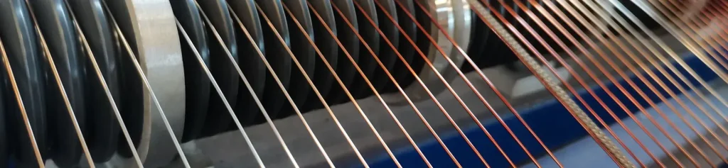
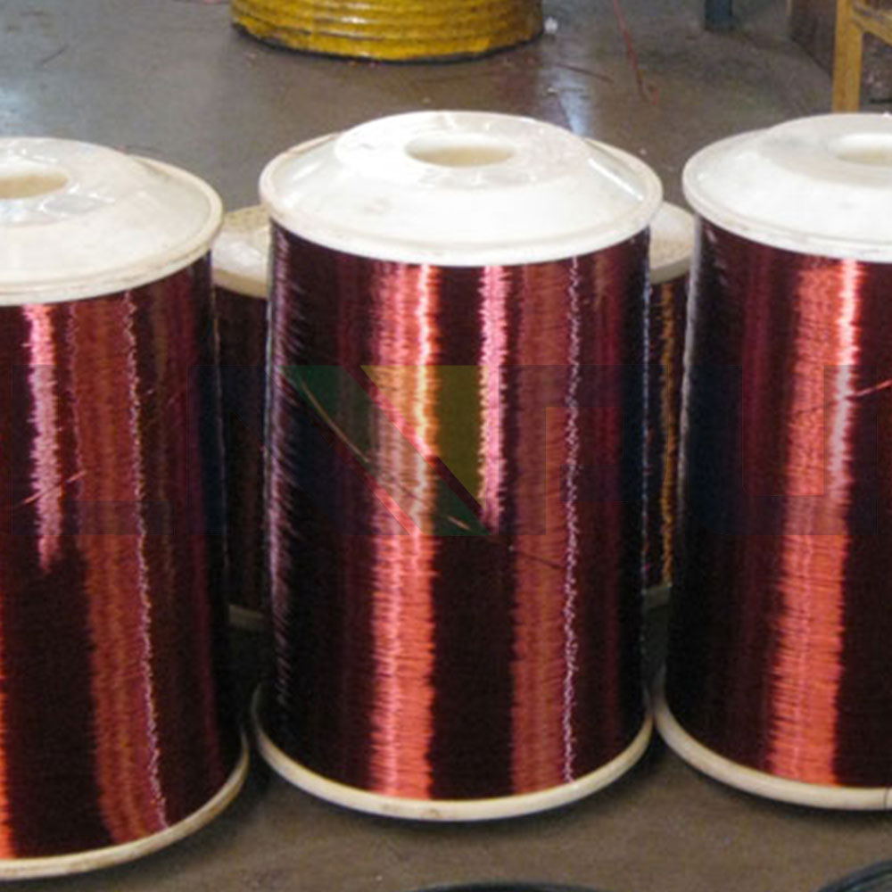
Hello, my name is Alex, and for the better part of two decades, my world has been one of coils, currents, and magnetics. If you were to ask me what single component has been both my greatest ally and my most formidable foe, I wouldn’t hesitate: 35 gauge (AWG) copper magnet wire.
On paper, it’s unassuming. A mere 0.143mm (0.0056 inches) in diameter. But in the real world of winding custom inductors, high-frequency transformers, and delicate sensor coils, this slender thread of copper is a master of deception. It promises incredible winding density and performance but delivers frustration and failure to the unprepared.
Countless articles will give you the specifications—the resistance per meter, the current rating, the standard insulation types. But they won’t convey the gut-wrenching snap of the wire in the middle of a 5,000-turn winding. They won’t describe the smell of burnt polyurethane insulation from a soldering iron held a half-second too long. And they certainly won’t teach you the “feel” of perfect tension that only comes after countless hours of practice and observation.
This isn’t another datasheet. This is a collection of my scars, my “aha!” moments, and the hard-won wisdom I’ve accumulated. This is my guide to truly mastering 35 gauge wire, built on first-hand experience.
The Engineer’s Dilemma: Why 35 AWG is Both a Miracle and a Menace
Every engineer or serious hobbyist is drawn to 35 AWG for its obvious benefits—the “miracle” part of the equation.
However, the properties that make it a miracle are precisely what make it a menace. The datasheet tells you the what, but not the why you should be cautious:
My Costliest Mistake: The Phantom Short in a High-Performance Audio Transformer
Early in my career, I was tasked with designing and prototyping a series of small-signal audio transformers. To meet the required inductance and frequency response, 35 AWG wire was the only choice. I spent a full day meticulously winding a prototype with thousands of turns, feeling proud of the neat, even layers.
The initial DC resistance test passed. The inductance measurement was spot on. But when we swept it with a signal generator, the performance curve was a disaster. There was a significant drop-off in the high frequencies and a strange, intermittent hiss.
After two days of exhaustive diagnostics, we finally found the culprit using a high-voltage insulation tester: a microscopic layer-to-layer short circuit. It was a phantom, only manifesting under specific dynamic conditions.
What went wrong? My post-mortem revealed two critical errors:
That failure was expensive, but the lesson was priceless. It taught me that working with 35 gauge wire isn’t about winding; it’s about creating a pristine, controlled environment for a very delicate material.
My Core Principles for Taming 35 AWG Wire
From that failure and countless projects since, I’ve developed three core principles. If you master these, you will succeed.
1. Tension is Everything: The “Whisper-Touch” Approach
Tension is the single most critical factor. The goal is the minimum tension required to create a neat, non-slumping coil.
2. Soldering: The One-Second Rule
Soldering this wire, especially the common solderable polyurethane type, is an art.
3. Insulation Integrity: Become a Forensic Inspector
You must treat the enamel insulation like the fragile shell of an egg.
Pro-Tips and Advanced Insights
Final Thoughts: From Frustration to Finesse
35 gauge copper magnet wire demands respect. It’s a material that will unforgivingly punish carelessness but will reward patience and attention to detail with exceptional performance. The datasheet provides the map, but true mastery comes from learning the terrain through hands-on experience.
So, the next time you pick up a spool of this fine wire, don’t just see its specifications. See it as a challenge—a test of your skill, your patience, and your process. Embrace the meticulous preparation, perfect your technique, and you’ll be able to create components that are not only functional but are truly works of precision engineering.